| Internet-Draft | Set Union | January 2021 |
| Summermatter & Grothoff | Expires 27 July 2021 | [Page] |
- Workgroup:
- Independent Stream
- Internet-Draft:
- draft-summermatter-set-union-01
- Published:
- Intended Status:
- Informational
- Expires:
Byzantine Fault Tolerant Set Reconciliation
Abstract
This document contains a protocol specification for Byzantine fault-tolerant Set Reconciliation.
Status of This Memo
This Internet-Draft is submitted in full conformance with the provisions of BCP 78 and BCP 79.
Internet-Drafts are working documents of the Internet Engineering Task Force (IETF). Note that other groups may also distribute working documents as Internet-Drafts. The list of current Internet-Drafts is at https://datatracker.ietf.org/drafts/current/.
Internet-Drafts are draft documents valid for a maximum of six months and may be updated, replaced, or obsoleted by other documents at any time. It is inappropriate to use Internet-Drafts as reference material or to cite them other than as "work in progress."
This Internet-Draft will expire on 27 July 2021.
Copyright Notice
Copyright (c) 2021 IETF Trust and the persons identified as the document authors. All rights reserved.
This document is subject to BCP 78 and the IETF Trust's Legal Provisions Relating to IETF Documents (https://trustee.ietf.org/license-info) in effect on the date of publication of this document. Please review these documents carefully, as they describe your rights and restrictions with respect to this document. Code Components extracted from this document must include Simplified BSD License text as described in Section 4.e of the Trust Legal Provisions and are provided without warranty as described in the Simplified BSD License.
1. Introduction
This document describes a Byzantine fault-tolerant set reconciliation protocol used to efficient and securely synchronize two sets of elements between two peers.
This Byzantine fault-tolerant set reconciliation protocol can be used in a variety of applications. Our primary envisioned application domain is the distribution of revocation messages in the GNU Name System (GNS) [GNUNET] [GNS] . In GNS, key revocation messages are usually flooded across the peer-to-peer overlay network to all connected peers whenever a key is revoked. However, as peers may be offline or the network might have been partitioned, there is a need to reconcile revocation lists whenever network partitions are healed or peers go online. The GNU Name System uses the protocol described in this specification to efficiently distribute revocation messages whenever network partitions are healed. Another application domain for the protocol described in this specification are Byzantine fault-tolerant bulletin boards, like those required in some secure multiparty computations. A well-known example for secure multiparty computations are various E-voting protocols [CryptographicallySecureVoting] which use a bulletin board to share the votes and intermediate computational results. We note that for such systems, the set reconciliation protocol is merely a component of a multiparty consensus protocol, such as the one described in (FIXME-CITE: DOLD MS Thesis! Which paper is his MS thesis on fdold.eu).
The protocol described in this report is generic and suitable for a wide range of applicaitons. As a result, the internal structure of the elements in the sets must be defined and verified by the application using the protocol. This document thus does not cover the elemtn structure, except for imposing a limit on the maximum size of an element.
The protocol faces an inherent trade-off between minimizing the number of network round-trips and the number of bytes sent over the network. Thus, for the protocol to choose the right parameters for a given situation, applications using the protocol must provide a parameter that specifies the cost-ratio of round-trips vs. bandwidth usage. Given this trade-off factor, the protocol will then choose parameters that minimize the total execution cost. In particular, there is one major choice to be made, which is between sending the full set of elements, or just sending the elements that differ. In the latter case, our design is basically a concrete implementation of a proposal by Eppstein. [Eppstein]
We say that our set reconciliation protocol is Byzantine fault-tolerant because it provides cryptographic and probabilistic methods to discover if the other peer is dishonest or misbehaving.
The objective here is to limit resources wasted on malicious actors. Malicious actors could send malformed messages, including malformed set elements, claim to have much larger numbers of valid set elements than the actually hold, or request the retransmission of elements that they have already received in previous interactions. Bounding resources consumed by malicous actors is important to ensure that higher-level protocols can use set reconciliation and still meet their resource targets. This can be particularly critical in multi-round synchronous consensus protocols where peers that cannot answer in a timely fashion would have to be treated as failed or malicious.
To defend against some of these attacks, applications need to remember the number of elements previously shared with a peer, and offer a means to check that elements are well-formed. Applications may also be able to provide an upper bound on the total number of valid elements that may exist. For example, in E-voting, the number of eligible voters could be used to provide such an upper bound.
This document defines the normative wire format of resource records, resolution processes, cryptographic routines and security considerations for use by implementors. SETU requires a bidirectional secure communication channel between the two parties. Specification of the communication channel is out of scope of this document.
The key words "MUST", "MUST NOT", "REQUIRED", "SHALL", "SHALL NOT", "SHOULD", "SHOULD NOT", "RECOMMENDED", "MAY", and "OPTIONAL" in this document are to be interpreted as described in[RFC2119].
2. Background
2.1. Bloom Filters
A Bloom filter (BF) is a space-efficient datastructure to test if am element is part of a set of elements. Elements are identified by an element ID. Since a BF is a probabilistic datastructure, it is possible to have false-positives: when asked if an element is in the set, the answer from a BF is either "no" or "maybe".
A BF consists of L buckets. Every bucket is a binary value that can be either 0 or 1. All buckets are initialized to 0. A mapping function M is used to map each the ID of each element from the set to a subset of k buckets. M is non-injective and can thus map the same element multiple times to the same bucket. The type of the mapping function can thus be described by the following mathematical notation:
------------------------------------
# M: E->B^k
------------------------------------
# L = Number of buckets
# B = 0,1,2,3,4,...L-1 (the buckets)
# k = Number of buckets per element
# E = Set of elements
------------------------------------
Example: L=256, k=3
M('element-data') = {4,6,255}
A typical mapping function is constructed by hashing the element, for example using the well-known Section 2 of HKDF construction [RFC5869].
To add an element to the BF, the corresponding buckets under the map M are set to 1. To check if an element may be in the set, one tests if all buckets under the map M are set to 1.
Further in this document a bitstream outputted by the mapping function is represented by a set of numeric values for example (0101) = (2,4). In the BF the buckets are set to 1 if the corresponding bit in the bitstream is 1. If there is a collision and a bucket is already set to 1, the bucket stays 1.
In the following example the element M(element) = (1,3) has been added:
    bucket-0     bucket-1       bucket-2      bucket-3
+-------------+-------------+-------------+-------------+
|      0      |      1      |      0      |      1      |
+-------------+-------------+-------------+-------------+
Is easy to see that the M(element) = (0,3) could be in the BF bellow and M(element) = (0,2) can't be in the BF bellow:
    bucket-0     bucket-1       bucket-2      bucket-3
+-------------+-------------+-------------+-------------+
|      1      |      0      |      0      |      1      |
+-------------+-------------+-------------+-------------+
The parameters L and k depend on the set size and must be chosen carefully to ensure that the BF does not return too many false-positives.
It is not possible to remove an element from the BF because buckets can only be set to 1 or 0. Hence it is impossible to differentiate between buckets containing one or more elements. To remove elements from the BF a Counting Bloom Filter is required.
2.2. Counting Bloom Filter
A Counting Bloom Filter (CBF) is an extension of theBloom Filters. In the CBF, buckets are unsigned numbers instead of binary values. This allows the removal of an elements from the CBF.
Adding an element to the CBF is similar to the adding operation of the BF. However, instead of setting the bucket on hit to 1 the numeric value stored in the bucket is increased by 1. For example if two colliding elements M(element1) = (1,3) and M(element2) = (0,3) are added to the CBF, bucket 0 and 1 are set to 1 and bucket 3 (the colliding bucket) is set to 2:
    bucket-0     bucket-1       bucket-2      bucket-3
+-------------+-------------+-------------+-------------+
|      1      |      1      |      0      |      2      |
+-------------+-------------+-------------+-------------+
The counter stored in the bucket is also called the order of the bucket.
To remove an element form the CBF the counters of all buckets the element is mapped to are decreased by 1.
Removing M(element2) = (1,3) from the CBF above:
    bucket-0     bucket-1       bucket-2      bucket-3
+-------------+-------------+-------------+-------------+
|      1      |      0      |      0      |      1      |
+-------------+-------------+-------------+-------------+
In practice, the number of bits available for the counters is usually finite. For example, given a 4-bit counter, a CBF bucket would overflow once 16 elements are mapped to the same bucket. To efficiently handle this case, the maximum value (15 in our example) is considered to represent "infinity". Once the order of a bucket reaches "infinity", it is no longer incremented or decremented.
The parameters L and k and the number of bits allocated to the counters should depend on the set size. An IBF will degenerate when subjected to insert and remove iterations of different elements, and eventually all buckets will reach "infinity". The speed of the degradation will depend on the choice of L and k in relation to the number of elements stored in the IBF.
3. Invertible Bloom Filter
An Invertible Bloom Filter (IBF) is a further extension of theCounting Bloom Filter. An IBF extends the Counting Bloom Filter with two more operations: decode and set difference. This two extra operations are useful to efficiently extract small differences between large sets.
3.1. Structure
An IBF consists of a mapping function M and L buckets that each store a signed counter and an XHASH. An XHASH is the XOR of various hash values. As before, the values used for k, L and the number of bits used for the signed counter and the XHASH depend on the set size and various other trade-offs, including the CPU architecture.
If the IBF size is to small or the mapping function does not spread out the elements uniformly, the signed counter can overflow or underflow. As with the CBF, the "maximum" value is thus used to represent "infinite". As there is no need to distinguish between overflow and underflow, the most canonical representation of "infinite" would be the minimum value of the counter in the canonical 2-complement interpretation. For example, given a 4-bit counter a value of -8 would be used to represent "infinity".
            bucket-0     bucket-1       bucket-2      bucket-3
        +-------------+-------------+-------------+-------------+-------
  count |   COUNTER   |   COUNTER   |   COUNTER   |   COUNTER   |  C...
        +-------------+-------------+-------------+-------------+------
  idSum |    IDSUM    |    IDSUM    |    IDSUM    |     IDSUM   |  I...
        +-------------+-------------+-------------+-------------+------
hashSum |   HASHSUM   |   HASHSUM   |   HASHSUM   |    HASHSUM  |  H..
        +-------------+-------------+-------------+-------------+-------
3.2. Operations
When an IBF is created, all counters and IDSUM and HASHSUM values of all buckets are initialized to zero.
3.2.1. Insert Element
To add an element to a IBF, the element is mapped to a subset of k buckets using the mapping function M as described in the Bloom Filters section introducing BFs. For the buckets selected by the mapping function, the counter is increased by one and the IDSUM field is set to the XOR of the element ID and the previously stored IDSUM. Furthermore, the HASHSUM is set to the XOR of the hash of the element ID and the previously stored HASHSUM.
In the following example, the insert operation is illustrated using an element with the ID 0x0102 and a hash of 0x4242, and a second element with the ID 0x0304 and a hash of 0x0101.
Empty IBF:
            bucket-0     bucket-1       bucket-2      bucket-3
        +-------------+-------------+-------------+-------------+
  count |      0      |      0      |      0      |      0      |
        +-------------+-------------+-------------+-------------+
  idSum |    0x0000   |    0x0000   |    0x0000   |    0x0000   |
        +-------------+-------------+-------------+-------------+
hashSum |    0x0000   |    0x0000   |    0x0000   |    0x0000   |
        +-------------+-------------+-------------+-------------+
Insert first element: [0101] with ID 0x0102 and hash 0x4242:
            bucket-0     bucket-1       bucket-2      bucket-3
        +-------------+-------------+-------------+-------------+
  count |      0      |      1      |      0      |      1      |
        +-------------+-------------+-------------+-------------+
  idSum |    0x0000   |   0x0102    |    0x0000   |   0x0102    |
        +-------------+-------------+-------------+-------------+
hashSum |    0x0000   |   0x4242    |    0x0000   |   0x4242    |
        +-------------+-------------+-------------+-------------+
Insert second element: [1100] with ID 0x0304 and hash 0101:
            bucket-0     bucket-1       bucket-2      bucket-3
        +-------------+-------------+-------------+-------------+
  count |      1      |      2      |      0      |      1      |
        +-------------+-------------+-------------+-------------+
  idSum |    0x0304   |   0x0206    |    0x0000   |   0x0102    |
        +-------------+-------------+-------------+-------------+
hashSum |    0x0101   |   0x4343    |    0x0000   |   0x4242    |
        +-------------+-------------+-------------+-------------+
3.2.2. Remove Element
To remove an element from the IBF the element is again mapped to a subset of the buckets using M. Then all the counters of the buckets selected by M are reduced by one, the IDSUM is replaced by the XOR of the old IDSUM and the ID of the element being removed, and the HASHSUM is similarly replaced with the XOR of the old HASHSUM and the hash of the ID.
In the following example the remove operation for the element [1100] with the hash 0x0101 is demonstrated.
IBF with encoded elements:
            bucket-0     bucket-1       bucket-2      bucket-3
        +-------------+-------------+-------------+-------------+
  count |      1      |      2      |      0      |      1      |
        +-------------+-------------+-------------+-------------+
  idSum |    0x0304   |   0x0206    |    0x0000   |   0x0102    |
        +-------------+-------------+-------------+-------------+
hashSum |   0x0101    |   0x4343    |    0x0000   |   0x4242    |
        +-------------+-------------+-------------+-------------+
Remove element [1100] with ID 0x0304 and hash 0x0101 from the IBF:
            bucket-0     bucket-1       bucket-2      bucket-3
        +-------------+-------------+-------------+-------------+
  count |      0      |      1      |      0      |      1      |
        +-------------+-------------+-------------+-------------+
  idSum |    0x0000   |   0x0102    |    0x0000   |   0x0102    |
        +-------------+-------------+-------------+-------------+
hashSum |    0x0000   |   0x4242    |    0x0000   |   0x4242    |
        +-------------+-------------+-------------+-------------+
Note that it is possible to "remove" elements from an IBF that were never present in the IBF in the first place. A negative counter value is thus indicative of elements that were removed without having been added. Note that an IBF bucket counter of zero no longer warrants that an element mapped to that bucket is not present in the set: a bucket with a counter of zero can be the result of one element being added and a different element (mapped to the same bucket) being removed. To check that an element is not present requires a counter of zero and an IDSUM and HASHSUM of zero --- and some assurance that there was no collision due to the limited number of bits in IDSUM and HASHSUM. Thus, IBFs are not suitable to replace BFs or IBFs.
Buckets in an IBF with a counter of 1 or -1 are crucial for decoding an IBF, as they might represent only a single element, with the IDSUM being the ID of that element. Following Eppstein (CITE), we will call buckets that only represent a single element pure buckets. Note that due to the possibility of multiple insertion and removal operations affecting the same bucket, not all buckets with a counter of 1 or -1 are actually pure buckets. Sometimes a counter can be 1 or -1 because N elements mapped to that bucket were added while N-1 or N+1 different elements also mapped to that bucket were removed.
3.2.3. Decode IBF
Decoding an IBF yields the HASH of an element from the IBF, or failure.
A decode operation requires a pure bucket, that is a bucket to which M only mapped a single element, to succeed. Thus, if there is no bucket with a counter of 1 or -1, decoding fails. However, as a counter of 1 or -1 is not a guarantee that the bucket is pure, there is also a chance that the decoder returns an IDSUM value that is actually the XOR of several IDSUMs. This is primarily detected by checking that the HASHSUM is the hash of the IDSUM. Only if the HASHSUM also matches, the bucket could be pure. Additionally, one should check that the IDSUM value actually would be mapped by M to the respective bucket. If not, there was a hash collision.
The very rare case that after all these checks a bucket is still falsely identified as pure must be detected (say by determining that extracted element IDs do not match any actual elements), and addressed at a higher level in the protocol. As these failures are probabilistic and depend on element IDs and the IBF construction, they can typically be avoided by retrying with different parameters, such as a different way to assign element IDs to elements, using a larger value for L, or a different mapping function M. A more common scenario (especially if L was too small) is that IBF decoding fails because there is no pure bucket. In this case, the higher-level protocol also should retry using different parameters.
Suppose the IBF contains a pure bucket. In this case, the IDSUM in the bucket identifies a single element. Furthermore, it is then possible to remove that element from the IBF (by inserting it if the counter was negative, and by removing it if the counter was positive). This is likely to cause other buckets to become pure, allowing further elements to be decoded. Eventually, decoding should succeed with all counters and IDSUM and HASHSUM values reaching zero. However, it is also possible that an IBF only partly decodes and then decoding fails after yielding some elements.
In the following example the successful decoding of an IBF containing the two elements previously added in our running example.
IBF with the two encoded elements:
            bucket-0     bucket-1       bucket-2      bucket-3
        +-------------+-------------+-------------+-------------+
  count |      1      |      2      |      0      |      1      |
        +-------------+-------------+-------------+-------------+
  idSum |   0x0304    |   0x0206    |    0x0000   |   0x0102    |
        +-------------+-------------+-------------+-------------+
hashSum |   0x0101    |   0x4343    |    0x0000   |   0x4242    |
        +-------------+-------------+-------------+-------------+
In the IBF are two pure buckets to decode (bit-1 and bit-4) we choose to start with decoding bucket 1, we decode the element with the hash 1010 and we see that there is a new pure bucket created (bit-2)
            bucket-0     bucket-1       bucket-2      bucket-3
        +-------------+-------------+-------------+-------------+
  count |      0      |      1      |      0      |      1      |
        +-------------+-------------+-------------+-------------+
  idSum |    0x0000   |   0x0102    |    0x0000   |   0x0102    |
        +-------------+-------------+-------------+-------------+
hashSum |    0x0000   |   0x4242    |    0x0000   |   0x4242    |
        +-------------+-------------+-------------+-------------+
In the IBF only pure buckets are left, we choose to continue decoding bucket 2 and decode element with the hash 0x4242. Now the IBF is empty (all buckets have count 0) that means the IBF has successfully decoded.
            bucket-0     bucket-1       bucket-2      bucket-3
        +-------------+-------------+-------------+-------------+
  count |      0      |      0      |      0      |      0      |
        +-------------+-------------+-------------+-------------+
  idSum |    0x0000   |    0x0000   |    0x0000   |    0x0000   |
        +-------------+-------------+-------------+-------------+
hashSum |    0x0000   |    0x0000   |    0x0000   |    0x0000   |
        +-------------+-------------+-------------+-------------+
3.2.4. Set Difference
Given addition and removal as defined above, it is possible to define an operation on IBFs that computes an IBF representing the set difference. Suppose IBF1 represents set A, and IBF2 represents set B. Then this set difference operation will compute IBF3 which represents the set A - B --- without needing elements from set A or B. To calculate the IBF representing this set difference, both IBFs must have the same length L, the same number of buckets per element k and use the same map M. Given this, one can compute the IBF representing the set difference by taking the XOR of the IDSUM and HASHSUM values of the respective buckets and subtracting the respective counters. Care should be taken to handle overflows and underflows by setting the counter to "infinity" as necessary. The result is a new IBF with the same number of buckets representing the set difference.
This new IBF can be decoded as described in section3.2.3. The new IBF can have two types of pure buckets with counter set to 1 or -1. If the counter is set to 1 the element is missing in the secondary set, and if the counter is set to -1 the element is missing in the primary set.
To demonstrate the set difference operation we compare IBF-A with IBF-B and generate as described IBF-AB
IBF-A containing elements with hashes 0x0101 and 0x4242:
            bucket-0     bucket-1       bucket-2      bucket-3
        +-------------+-------------+-------------+-------------+
  count |      1      |      2      |      0      |      1      |
        +-------------+-------------+-------------+-------------+
  idSum |    0x0304   |   0x0206    |    0x0000   |   0x0102    |
        +-------------+-------------+-------------+-------------+
hashSum |    0x0101   |   0x4343    |    0x0000   |   0x4242    |
        +-------------+-------------+-------------+-------------+
IBF-B containing elements with hashes 0x4242 and 0x5050
            bucket-0     bucket-1       bucket-2      bucket-3
        +-------------+-------------+-------------+-------------+
  count |      0      |      1      |      1      |      1      |
        +-------------+-------------+-------------+-------------+
  idSum |    0x0000   |    0x0102   |    0x1345   |    0x0102    |
        +-------------+-------------+-------------+-------------+
hashSum |    0x0000   |    0x4242   |    0x5050   |    0x4242   |
        +-------------+-------------+-------------+-------------+
IBF-AB XOR value and subtract count:
            bucket-0     bucket-1       bucket-2      bucket-3
        +-------------+-------------+-------------+-------------+
  count |      1      |      1      |      -1     |      0      |
        +-------------+-------------+-------------+-------------+
  idSum |    0x0304   |    0x0304   |    0x1345   |    0x0000   |
        +-------------+-------------+-------------+-------------+
hashSum |    0x0101   |    0x0101   |    0x5050   |    0x0000   |
        +-------------+-------------+-------------+-------------+
After calculating and decoding the IBF-AB its clear that in IBF-A the element with the hash 0x5050 is missing (-1 in bit-3) while in IBF-B the element with the hash 0101 is missing (1 in bit-1 and bit-2). The element with hash 0x4242 is present in IBF-A and IBF-B and is removed by the set difference operation (bit-4).
3.3. Wire format
To facilitate a reasonably CPU-efficient implementation, this specification requires the IBF counter to always use 8 bits. Fewer bits would result in a paritcularly inefficient implementation, while more bits are rarely useful as sets with so many elements should likely be represented using a larger number of buckets. This means the counter of this design can reach a minimum of -127 and a maximum of 127 before the counter reaches "infinity" (-128).
For the "IDSUM", we always use a 64-bit representation. The IDSUM value must have sufficient entropy for the mapping function M to yield reasonably random buckets even for very large values of L. With a 32 bit value the chance that multiple elements may be mapped to the same ID would be quite high, even for moderately large sets. Using more than 64 bits would at best make sense for very large sets, but then it is likely always better to simply afford additional round trips to handle the occasional collision. 64 bits are also a reasonable size for many CPU architectures.
For the "HASHSUM", we always use a 32-bit representation. Here, it is mostly important to avoid collisions, where different elements are mapped to the same hash. However, we note that by design only a few elements (certainly less than 127) should ever be mapped to the same bucket, so a small number of bits should suffice. Furthermore, our protocol is designed to handle occasional collisions, so while with 32-bits there remains a chance of accidental collisions, at 32 bit the chance is generally believed to be sufficiently small enough for the protocol to handle those cases efficiently for a wide range of use-cases. Smaller hash values would safe bandwidth, but also drastically increase the chance of collisions. 32 bits are also again a reasonable size for many CPU architectures.
3.3.1. ID Calculation
The ID is generated as 64-bit output from a Section 2 of HKDF construction [RFC5869] with HMAC-SHA512 as XTR and HMAC-SHA256 as PRF and salt is set to the unsigned 64-bit equivalent of 0. The output is then truncated to 64-bit. Its important that the elements can be redistributed over the buckets in case the IBF does not decode, that's why the ID is salted with a random salt given in the SALT field of this message. Salting is done by calculation the a random salt modulo 64 (using only the lowest 6-bits of the salt) and do a bitwise right rotation of output of KDF by the 6-bit salts numeric representation.
Representation in pseudocode:
# INPUTS:
# key: Pre calculated and truncated key from id_calculation function
# ibf_salt: Salt of the IBF
# OUTPUT:
# value: salted key
FUNCTION salt_key(key,ibf_salt):
  s = ibf_salt % 64;
  k = key

  /* rotate ibf key */
  k = (k >> s) | (k << (64 - k))
  return key


# INPUTS:
# element: Element to calculated id from.
# salt: Salt of the IBF
# OUTPUT:
# value: the ID of the element

FUNCTION id_calculation (element,ibf_salt):
    salt = 0
    XTR=HMAC-SHA256
    PRF=HMAC-SHA256
    key = HKDF(XTR, PRF, salt, element)
    key = key modulo 2^64 // Truncate
    return salt_key(key,ibf_salt)
3.3.2. Mapping Function
The mapping function M as described above in the figure Figure 1 decides in which buckets the ID and HASH have to be binary XORed to. In practice there the following algorithm is used:
The first index is simply the HASH modulo the IBF size. The second index is calculated by creating a new 64-bit value by shifting the 32-bit value left and setting the lower 32-bit to the number of indexes already processed. From the resulting 64-bit value a CRC32 checksum is created the second index is now the modulo of the CRC32 output this is repeated until the predefined amount indexes is generated. In the case a index is hit twice, which would mean this bucket could not get pure again, the second hit is just skipped and the next iteration is used as.
# INPUTS:
# key: Is the ID of the element calculated in the id_calculation function above.
# number_of_buckets_per_element: Pre-defined count of buckets elements are inserted into
# ibf_size: the size of the ibf (count of buckets)
# OUTPUT:
# dst: Array with bucket IDs to insert ID and HASH

FUNCTION get_bucket_id (key, number_of_buckets_per_element, ibf_size)
  bucket = CRC32(key)

  i = 0
  filled = 0
  WHILE filled < number_of_buckets_per_element

    element_already_in_bucket = false
    j = 0
    WHILE j < filled
      IF dst[j] == bucket modulo ibf_size THEN
        element_already_in_bucket = true
      ENDIF
      j++
    ENDWHILE

    IF !element_already_in_bucket THEN
        dst[filled++] = bucket modulo ibf_size
    ENDIF

    x = (bucket << 32) | i
    bucket = CRC32(x)

    i++
  ENDWHILE
  return dst
3.3.3. HASH calculation
The HASH is calculated by calculating the CRC32 checksum of the 64-bit ID value which returns a 32-bit value.
4. Strata Estimator
4.1. Description
Strata Estimators help estimate the size of the set difference between two set of elements. This is necessary to efficiently determinate the tuning parameters for an IBF, in particular a good value for L.
Basically a Strata Estimator (SE) is a series of IBFs (with a rather small value of L) in which increasingly large subsets of the full set of elements are added to each IBF. For the n-th IBF, the function selecting the subset of elements should sample to select (probabilistically) 1/(2^n) of all elements. This can be done by counting the number of trailing bits set to "1" in an element ID, and then inserting the element into the IBF identified by that counter. As a result, all elements will be mapped to one IBF, with the n-th IBF being statistically expected to contain 1/(2^n) elements.
Given two SEs, the set size difference can be estimated by trying to decode all of the IBFs. Given that L was set to a rather small value, IBFs containing large strata will likely fail to decode. For those IBFs that failed to decode, one simply extrapolates the number of elements by scaling the numbers obtained from the other IBFs that did decode. If none of the IBFs of the SE decoded (which given a reasonable choice of L should be highly unlikely), one can retry using a different mapping function M.
5. Mode of operation
The set union protocol uses IBFs and SEs as primitives. Depending on the state of the two sets there are different strategies or operation modes how to efficiently determinate missing elements between the two sets.
The simplest mode is the "full" synchronization mode. The idea is that if the difference between the sets of the two peers exceeds a certain threshold, the overhead to determine which elements are different outweighs the overhead of sending the complete set. In this case, the most efficient method can be to just exchange the full sets.
Link to statemachine diagram 
The second possibility is that the difference of the sets is small compared to the set size. Here, an efficient "delta" synchronization mode is more efficient. Given these two possibilities, the first steps of the protocol are used to determine which mode should be used.
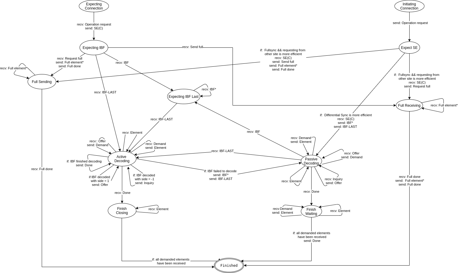
Thus, the set synchronization protocol always begins with the following operation mode independent steps.
The initiating peer begins in the Initiating Connection state and the receiving peer in the Expecting Connection state. The first step for the initiating peer in the protocol is to send an Operation Request to the receiving peer and transition into the Expect SE state. After receiving the Operation Request the receiving peer transitions to the Expecting IBF state and answers with the Strata Estimator message. When the initiating peer receives the Strata Estimator message, it decides with some heuristics which operation mode is likely more suitable for the estimated set difference and the application-provided latency-bandwidth tradeoff. The detailed tradeoff between the Full Synchronisation Mode and the Delta Synchronisation Mode is explained in the sectionCombined Mode.
5.1. Full Synchronisation Mode
When the initiating peer decides to use the full synchronisation mode and the set of the initiating peer is bigger than the set of the receiving peer, the initiating peer sends a Request Full message, and transitions from Expecting SE to the Full Receiving state. If the set of the initiating peer is smaller, it sends all set elements to the other peer followed by the Full Done message, and transitions into the Full Sending state.
Link to statemachine diagram 
The behavior of the participants the different state is described below:
- Expecting IBF:
- If a peer in the Expecting IBF state receives a Request Full message from the other peer, the peer sends all the elements of its set followed by a Full Done message to the other peer, and transitions to the Full Sending state. If the peer receives an Full Element message, it processes the element and transitions to the Full Receiving state.
- Full Sending:
- While a peer is in Full Sending state the peer expects to continuously receive elements from the other peer. As soon as a the Full Done message is received, the peer transitions into the Finished state.
- Full Receiving (In code: Expecting IBF):
- While a peer is in the Full Receiving state, it expects to continuously receive elements from the other peer. As soon as a the Full Done message is received, it sends the remaining elements (those it did not receive) from its set to the other peer, followed by a Full Done . After sending the last message, the peer transitions into the Finished state.
5.2. Delta Synchronisation Mode
When the initiating peer in the Expected SE state decides to use the delta synchronisation mode, it sends a IBF to the receiving peer and transitions into the Passive Decoding state.
The receiving peer in the Expecting IBF state receives the IBF message from the initiating peer and transitions into the Expecting IBF Last state when there are multiple IBF messages to sent, when there is just a single IBF message the reviving peer transitions directly to the Active Decoding state.
The peer that is in the Active Decoding, Finish Closing or in the Expecting IBF Last state is called the active peer and the peer that is in either the Passive Decoding or the Finish Waiting state is called the passive peer.
Link to statemachine diagram 
The behavior of the participants the different states is described below:
- Passive Decoding:
-
In the Passive Decoding state the passive peer reacts to requests from the active peer. The action the passive peer executes depends on the message the passive peer receives in the Passive Decoding state from the active peer and is described below on a per message basis.
- Inquiry message:
- The Inquiry message is received if the active peer requests the SHA-512 hash of one or more elements (by sending the 64 bit element ID) that are missing from the active peer's set. In this case the passive peer answers with Offer messages which contain the SHA-512 hash of the requested element. If the passive peer does not have an element with a matching element ID, it MUST ignore the inquiry. If multiple elements match the 64 bit element ID, the passive peer MUST send offers for all of the matching elements.
- Demand message:
- The Demand message is received if the active peer requests a complete element that is missing in the active peers set. If the requested element is valid the passive peer answers with an Elements message which contains the full, application-dependent data of the requested element. If the passive peer receives a demand for a SHA-512 hash for which it has no element, a protocol violation is detected and the protocol MUST be aborted. Implementations MAY strengthen this and forbid demands without previous matching offers.
- Offer message:
- The Offer message is received if the active peer has decoded an element that is present in the active peers set and may be missing in the set of the passive peer. If the SHA-512 hash of the offer is indeed not a hash of any of the elements from the set of the passive peer, the passive peer MUST answer with a Demand message for that SHA-512 hash and remember that it issued this demand. The send demand need to be added to a list with unsatisfied demands.
- Elements message:
- When a new element message has been received the peer checks if a corresponding Demand for the element has been sent and the demand is still unsatisfied. If the element has been demanded the peer checks the element for validity, removed it from the list of pending demands and then then saves the element to the the set otherwise the peer rejects the element.
- IBF message:
- If an IBF message is received, this indicates that decoding of the IBF on the active site has failed and roles should be swapped. The receiving passive peer transitions into the Expecting IBF Last state, and waits for more IBF messages or the final IBF message to be received.
- IBF message:
- If an IBF message is received this indicates that the there is just one IBF slice and a direct state and role transition from Passive Decoding to Active Decoding is initiated.
- Done message:
- Receiving the Done message signals the passive peer that all demands of the active peer have been satisfied. Alas, the active peer will continue to process demands from the passive peer. Upon receiving this message, the passive peer transitions into the Finish Waiting state.
- Active Decoding:
-
In the Active Decoding state the active peer decodes the IBFs and evaluates the set difference between the active and passive peer. Whenever an element ID is obtained by decoding the IBF, the active peer sends either an offer or an inquiry to the passive peer, depending on which site the decoded element is missing.
If the IBF decodes a positive (1) pure bucket, the element is missing on the passive peers site. Thus the active peer sends an Offer to the passive peer. A negative (-1) pure bucket indicates that a element is missing in the active peers set, so the active peer sends a Inquiry to the passive peer.
In case the IBF does not successfully decode anymore, the active peer sends a new IBF to the passive client and changes into Passive Decoding state. This initiates a role swap. To reduce overhead and prevent double transmission of offers and elements the new IBF is created on the new complete set after all demands and inquiries have been satisfied.
As soon as the active peer successfully finished decoding the IBF, the active peer sends a Done message to the passive peer.
All other actions taken by the active peer depend on the message the active peer receives from the passive peer. The actions are described below on a per message basis:
- Offer message:
- The Offer message indicates that the passive peer received a Inquiry message from the active peer. If a Inquiry has been sent and the offered element is missing in the active peers set, the active peer sends a Demand message to the passive peer. The send demand need to be added to a list with unsatisfied demands. In the case the received offer is for an element that is already in the set of the peer the offer is ignored.
- Demand message:
- The Demand message indicates that the passive peer received a Offer from the active peer. The active peer satisfies the demand of the passive peer by sending Elements message if a offer request for the element has been sent. In the case the demanded element does not exist in the set there was probably a bucket decoded that was not really pure so potentially all Offer and Demand messages sent after are invalid in this case a role change active -> passive with a new IBF is easiest. If a demand for the same element is received multiple times the demands should be discarded.
- Elements message:
- A element that is received is marked in the list of demanded elements as satisfied, validated and saved and not further action is taken. Elements that are not demanded or already known are discarded.
- Done message:
- Receiving the message Done indicates that all demands of the passive peer have been satisfied. The active peer then changes into the state Finish Closing state. If the IBF is not finished decoding and the Done is received the other peer is not in compliance with the protocol and the set reconciliation MUST be aborted.
- Expecing IBF Last
-
In the Expecing IBF Last state the active peer continuously receives IBF messages from the passive peer. When the last IBF message is received the active peer changes into Active Decoding state.
- Finish Closing / Finish Waiting
-
In this states the peers are waiting for all demands to be satisfied and for the synchronisation to be completed. When all demands are satisfied the peer changes into state Finished.
5.3. Combined Mode
In the combined mode the Full Synchronisation Mode and the Delta Synchronisation Mode are combined to minimize resource consumption.
The Delta Synchronisation Mode is only efficient on small set differences or if the byte-size of the elements is large. Is the set difference is estimated to be large the Full Synchronisation Mode is more efficient. The exact heuristics and parameters on which the protocol decides which mode should be used are described in the section of this document.
There are two main cases when a Full Synchronisation Mode is always used. The first case is when one of the peers announces having an empty set. This is announced by setting the SETSIZE field in the Strata Estimator to 0. The second case is if the application requested full synchronization explicitly. This is useful for testing and should not be used in production.
6. Messages
6.1. Operation Request
6.1.1. Description
This message is the first message of the protocol and it is sent to signal to the receiving peer that the initiating peer wants to initialize a new connection.
This message is sent in the transition between the Initiating Connection state and the Expect SE state.
If a peer receives this message and is willing to run the protocol, it answers by sending back a Strata Estimator message. Otherwise it simply closes the connection.
6.1.2. Structure
        0     8     16    24    32    40    48    56
        +-----+-----+-----+-----+-----+-----+-----+-----+
        |  MSG SIZE |  MSG TYPE |    ELEMENT COUNT      |
        +-----+-----+-----+-----+-----+-----+-----+-----+
        |                      APX
        +-----+-----+-----+-----+-----+-----+-----+-----+                                               /
        /                                               /
        /                                               /
where:
- MSG SIZE
- is 16-bit unsigned integer in network byte order witch describes the message size in bytes and the header is included.
- MSG TYPE
- the type of SETU_P2P_OPERATION_REQUEST as registered inGANA Considerations, in network byte order.
- ELEMENT COUNT
- is the number of the elements the requesting party has in its set, as a 32-bit unsigned integer in network byte order.
- APX
- is a SHA-512 hash that identifies the application.
6.2. IBF
6.2.1. Description
The IBF message contains a slice of the IBF.
The IBF message is sent at the start of the protocol from the initiating peer in the transaction between Expect SE -> Expecting IBF Last or when the IBF does not decode and there is a role change in the transition between Active Decoding -> Expecting IBF Last. This message is only sent if there are more than one IBF slice to sent, in the case there is just one slice the IBF message is sent.
6.2.2. Structure
        0     8     16    24    32    40    48    56
        +-----+-----+-----+-----+-----+-----+-----+-----+
        |  MSG SIZE |  MSG TYPE |ORDER|       PAD       |
        +-----+-----+-----+-----+-----+-----+-----+-----+
        |         OFFSET        |          SALT         |
        +-----+-----+-----+-----+-----+-----+-----+-----+
        |                  IBF-SLICE
        +                                               /
        /                                               /
        /                                               /
where:
- MSG SIZE
- is 16-bit unsigned integer in network byte order witch describes the message size in bytes and the header is included.
- MSG TYPE
- the type of SETU_P2P_REQUEST_IBF as registered in GANA Considerations in network byte order.
- ORDER
- is a 8-bit unsigned integer which signals the order of the IBF. The order of the IBF is defined as the logarithm of the number of buckets of the IBF.
- PAD
- is 24-bit always set to zero
- OFFSET
- is a 32-bit unsigned integer which signals the offset to the following ibf slices in the original.
- SALT
- is a 32-bit unsigned integer that contains the salt which was used to create the IBF.
- IBF-SLICE
-
are variable count of slices in an array. A single slice contains out multiple 64-bit IDSUMS, 32-bit HASHSUMS and 8-bit COUNTERS. In the network order the array of IDSUMS is first, followed by an array of HASHSUMS and ended with an array of COUNTERS. Length of the array is defined by MIN( 2^ORDER - OFFSET, MAX_BUCKETS_PER_MESSAGE). MAX_BUCKETS_PER_MESSAGE is defined as 32768 divided by the BUCKET_SIZE which is 13-byte (104-bit).
To get the IDSUM field, all IDs who hit a bucket are added up with a binary XOR operation. See ID Calculation for details about ID generation.
The calculation of the HASHSUM field is done accordingly to the calculation of the IDSUM field: all HASHes are added up with a binary XOR operation. The HASH value is calculated as described in detail in sectionHASH calculation.
The algorithm to find the correct bucket in which the ID and the HASH have to be added is described in detail in sectionMapping Function.
                             IBF-SLICE
        0     8     16    24    32    40    48    56
        +-----+-----+-----+-----+-----+-----+-----+-----+
        |                    IDSUMS                     |
        +-----+-----+-----+-----+-----+-----+-----+-----+
        |                    IDSUMS                     |
        +-----+-----+-----+-----+-----+-----+-----+-----+
        |         HASHSUMS      |        HASHSUMS       |
        +-----+-----+-----+-----+-----+-----+-----+-----+
        |        COUNTERS       |       COUNTERS        |
        +-----+-----+-----+-----+-----+-----+-----+-----+
        /                                               /
        /                                               /
6.3. IBF
6.3.1. Description
This message indicates to the remote peer that all slices of the bloom filter have been sent. The binary structure is exactly the same as the Structure of the message IBF with a different "MSG TYPE" which is defined in GANA Considerations "SETU_P2P_IBF_LAST".
Receiving this message initiates the state transmissions Expecting IBF Last -> Active Decoding, Expecting IBF -> Active Decoding and Passive Decoding -> Active Decoding. This message can initiate a peer the roll change from Active Decoding to Passive Decoding.
6.4. Elements
6.4.1. Description
The Element message contains an element that is synchronized in the Delta Synchronisation Mode and transmits a full element between the peers.
This message is sent in the state Active Decoding and Passive Decoding as answer to a Demand message from the remote peer. The Element message can also be received in the Finish Closing or Finish Waiting state after receiving a Done message from the remote peer, in this case the client changes to the Finished state as soon as all demands for elements have been satisfied.
This message is exclusively sent in theDelta Synchronisation Mode.
6.4.2. Structure
        0     8     16    24    32    40    48    56
        +-----+-----+-----+-----+-----+-----+-----+-----+
        |  MSG SIZE |  MSG TYPE |   E TYPE  |  PADDING  |
        +-----+-----+-----+-----+-----+-----+-----+-----+
        |   E SIZE  |   AE TYPE |           DATA
        +-----+-----+-----+-----+                       /
        /                                               /
        /                                               /
where:
- MSG SIZE
- is 16-bit unsigned integer in network byte order witch describes the message size in bytes and the header is included.
- MSG TYPE
- the type of SETU_P2P_ELEMENTS as registered in GANA Considerations in network byte order.
- E TYPE
- element type is a 16-bit unsigned integer witch defines the element type for the application.
- PADDING
- is 16-bit always set to zero
- E SIZE
- element size is 16-bit unsigned integer that signals the size of the elements data part.
- AE TYPE
- application specific element type is a 16-bit unsigned integer that is needed to identify the type of element that is in the data field
- DATA
- is a field with variable length that contains the data of the element.
6.5. Offer
6.5.1. Description
The offer message is an answer to an Inquiry message and transmits the full hash of an element that has been requested by the other peer. This full hash enables the other peer to check if the element is really missing in its set and eventually sends a Demand message for that a element.
The offer is sent and received only in the Active Decoding and in the Passive Decoding state.
This message is exclusively sent in theDelta Synchronisation Mode.
6.5.2. Structure
        0     8     16    24    32    40    48    56
        +-----+-----+-----+-----+-----+-----+-----+-----+
        |  MSG SIZE |  MSG TYPE |         HASH
        +-----+-----+-----+-----+
        /                                               /
        /                                               /
where:
- MSG SIZE
- is 16-bit unsigned integer in network byte order witch describes the message size in bytes and the header is included.
- MSG TYPE
- the type of SETU_P2P_OFFER as registered in GANA Considerations in network byte order.
- HASH
- is a SHA 512-bit hash of the element that is requested with a inquiry message.
6.6. Inquiry
6.6.1. Description
The Inquiry message is exclusively sent by the active peer in Active Decoding state to request the full hash of an element that is missing in the active peers set. This is normally answered by the passive peer with Offer message.
This message is exclusively sent in theDelta Synchronisation Mode.
NOTE: HERE IS AN IMPLEMENTATION BUG UNNECESSARY 32-BIT PADDING!
6.6.2. Structure
        0     8     16    24    32    40    48    56
        +-----+-----+-----+-----+-----+-----+-----+-----+
        |  MSG SIZE |  MSG TYPE |          SALT         |
        +-----+-----+-----+-----+-----+-----+-----+-----+
        |                    IBF KEY                    |
        +-----+-----+-----+-----+-----+-----+-----+-----+
where:
- MSG SIZE
- is 16-bit unsigned integer in network byte order witch describes the message size in bytes and the header is included.
- MSG TYPE
- the type of SETU_P2P_INQUIRY as registered in GANA Considerations in network byte order.
- IBF KEY
- is a 64-bit unsigned integer that contains the key for which the inquiry is sent.
6.7. Demand
6.7.1. Description
The demand message is sent in the Active Decoding and in the Passive Decoding state. It is a answer to a received Offer message and is sent if the element described in the Offer message is missing in the peers set. In the normal workflow the answer to the demand message is an Elements message.
This message is exclusively sent in theDelta Synchronisation Mode.
6.7.2. Structure
        0     8     16    24    32    40    48    56
        +-----+-----+-----+-----+-----+-----+-----+-----+
        |  MSG SIZE |  MSG TYPE |          HASH
        +-----+-----+-----+-----+
        /                                               /
        /                                               /
where:
- MSG SIZE
- is 16-bit unsigned integer in network byte order witch describes the message size in bytes and the header is included.
- MSG TYPE
- the type of SETU_P2P_DEMAND as registered in GANA Considerations in network byte order.
- HASH
- is a 512-bit Hash of the element that is demanded.
6.8. Done
6.8.1. Description
The done message is sent when all Demand messages have been successfully satisfied and the set is complete synchronized. A final checksum (XOR SHA-512 hash) over all elements of the set is added to the message to allow the other peer to make sure that the sets are equal.
This message is exclusively sent in theDelta Synchronisation Mode.
6.8.2. Structure
        0     8     16    24    32    40    48    56
        +-----+-----+-----+-----+-----+-----+-----+-----+
        |  MSG SIZE |  MSG TYPE | HASH
        +-----+-----+-----+-----+
where:
- MSG SIZE
- is 16-bit unsigned integer in network byte order witch describes the message size in bytes and the header is included.
- MSG TYPE
- the type of SETU_P2P_DONE as registered in GANA Considerations in network byte order.
- HASH
- is a 512-bit hash of the set to allow a final equality check.
6.9. Full Done
6.9.1. Description
The full done message is sent in the Full Synchronisation Mode to signal that all remaining elements of the set have been sent. The message is received and sent in in the Full Sending and in the Full Receiving state. When the full done message is received in Full Sending state the peer changes directly into Finished state. In Full Receiving state receiving a full done message initiates the sending of the remaining elements that are missing in the set of the other peer.
6.9.2. Structure
        0     8     16    24    32
        +-----+-----+-----+-----+
        |  MSG SIZE |  MSG TYPE |
        +-----+-----+-----+-----+
where:
- MSG SIZE
- is 16-bit unsigned integer in network byte order witch describes the message size in bytes and the header is included.
- MSG TYPE
- the type of SETU_P2P_FULL_DONE as registered in GANA Considerations in network byte order.
6.10. Request Full
6.10.1. Description
The request full message is sent by the initiating peer in Expect SE state to the receiving peer if the operation mode "Full Synchronisation Mode" is determined as the better Mode of operation and the set size of the initiating peer is smaller than the set size of the receiving peer. The initiating peer changes after sending the request full message into Full Receiving state.
The receiving peer receives the Request Full message in the Expecting IBF, afterwards the receiving peer starts sending its complete set in Full Element messages to the initiating peer.
6.10.2. Structure
        0     8     16    24    32
        +-----+-----+-----+-----+
        |  MSG SIZE |  MSG TYPE |
        +-----+-----+-----+-----+
where:
- MSG SIZE
- is 16-bit unsigned integer in network byte order witch describes the message size in bytes and the header is included.
- MSG TYPE
- the type of SETU_P2P_REQUEST_FULL as registered in GANA Considerations in network byte order.
6.11. Strata Estimator
6.11.1. Description
The strata estimator is sent by the receiving peer at the start of the protocol right after the Operation Request message has been received.
The strata estimator is used to estimate the difference between the two sets as described in section4.
When the initiating peer receives the strata estimator the peer decides which Mode of operation to use for the synchronization. Depending on the size of the set difference and the Mode of operation the initiating peer changes into Full Sending, Full Receiving or Passive Decoding state.
6.11.2. Structure
        0     8     16    24    32    40    48    56
        +-----+-----+-----+-----+-----+-----+-----+-----+
        |  MSG SIZE |  MSG TYPE |        SETSIZE
        +-----+-----+-----+-----+-----+-----+-----+-----+
              SETSIZE           |          SE-SLICES
        +-----+-----+-----+-----+
        /                                               /
        /                                               /
where:
- MSG SIZE
- is 16-bit unsigned integer in network byte order witch describes the message size in bytes and the header is included.
- MSG TYPE
- the type of SETU_P2P_SE as registered in GANA Considerations in network byte order.
- SETSIZE
- is a 64-bit unsigned integer that is defined by the size of the set the SE is
- SE-SLICES
- is variable in size and contains the same structure as the IBF-SLICES field in the IBF message.
6.12. Strata Estimator Compressed
6.12.1. Description
The Strata estimator can be compressed with gzip to improve performance. For details see section.
Since the content of the message is the same as the uncompressed Strata Estimator, the details aren't repeated here for details see section6.11.
6.13. Full Element
6.13.1. Description
The full element message is the equivalent of the Elements message in theFull Synchronisation Mode. It contains a complete element that is missing in the set of the peer that receives this message.
The full element message is exclusively sent in the transitions Expecting IBF -> Full Receiving and Full Receiving -> Finished. The message is only received in the Full Sending and Full Receiving state.
After the last full element messages has been sent the Full Done message is sent to conclude the full synchronisation of the element sending peer.
6.13.2. Structure
        0     8     16    24    32    40    48    56
        +-----+-----+-----+-----+-----+-----+-----+-----+
        |  MSG SIZE |  MSG TYPE |   E TYPE  |  PADDING  |
        +-----+-----+-----+-----+-----+-----+-----+-----+
        |    SIZE   |   AE TYPE |  DATA
        +-----+-----+-----+-----+
        /                                               /
        /                                               /
where:
- MSG SIZE
- is 16-bit unsigned integer in network byte order witch describes the message size in bytes and the header is included.
- MSG TYPE
- the type of SETU_P2P_REQUEST_FULL_ELEMENT as registered in GANA Considerations in network byte order.
- E TYPE
- element type is a 16-bit unsigned integer witch defines the element type for the application.
- PADDING
- is 16-bit always set to zero
- E SIZE
- element size is 16-bit unsigned integer that signals the size of the elements data part.
- AE TYPE
- application specific element type is a 16-bit unsigned integer that is needed to identify the type of element that is in the data field
- DATA
- is a field with variable length that contains the data of the element.
7. GANA Considerations
GNUnet Assigned Numbers Authority (GANA) is requested to amend the "GNUnet Message Type" registry as follows:
Type    | Name                       | References | Description
--------+----------------------------+------------+--------------------------
 559    | SETU_P2P_REQUEST_FULL      | [This.I-D] | Request the full set of the other peer
 560    | SETU_P2P_DEMAND            | [This.I-D] | Demand the whole element from the other peer, given only the hash code.
 561    | SETU_P2P_INQUIRY           | [This.I-D] | Tell the other peer to send us a list of hashes that match an IBF key.
 562    | SETU_P2P_OFFER             | [This.I-D] | Tell the other peer which hashes match a given IBF key.
 563    | SETU_P2P_OPERATION_REQUEST | [This.I-D] | Request a set union operation from a remote peer.
 564    | SETU_P2P_SE                | [This.I-D] | Strata Estimator uncompressed
 565    | SETU_P2P_IBF               | [This.I-D] | Invertible Bloom Filter Slice.
 566    | SETU_P2P_ELEMENTS          | [This.I-D] | Actual set elements.
 567    | SETU_P2P_IBF_LAST          | [This.I-D] | Invertible Bloom Filter Last Slice.
 568    | SETU_P2P_DONE              | [This.I-D] | Set operation is done.
 569    | SETU_P2P_SEC               | [This.I-D] | Strata Estimator compressed
 570    | SETU_P2P_FULL_DONE         | [This.I-D] | All elements in full synchronization mode have been send is done.
 571    | SETU_P2P_FULL_ELEMENT      | [This.I-D] | Send an actual element in full synchronization mode.
8. Contributors
The original GNUnet implementation of the Byzantine Fault Tolerant Set Reconciliation protocol has mainly been written by Florian Dold and Christian Grothoff.
9. Normative References
- [RFC5869]
- Krawczyk, H. and P. Eronen, "HMAC-based Extract-and-Expand Key Derivation Function (HKDF)", RFC 5869, DOI 10.17487/RFC5869, , <https://www.rfc-editor.org/info/rfc5869>.
- [RFC2119]
- Bradner, S., "Key words for use in RFCs to Indicate Requirement Levels", BCP 14, RFC 2119, DOI 10.17487/RFC2119, , <https://www.rfc-editor.org/info/rfc2119>.
- [GANA]
- GNUnet e.V., "GNUnet Assigned Numbers Authority (GANA)", , <https://gana.gnunet.org/>.
- [CryptographicallySecureVoting]
- Dold, F., "Cryptographically Secure, DistributedElectronic Voting", <https://git.gnunet.org/bibliography.git/plain/docs/ba_dold_voting_24aug2014.pdf>.
- [GNUNET]
- Wachs, M., Schanzenbach, M., and C. Grothoff, "A Censorship-Resistant, Privacy-Enhancing andFully Decentralized Name System", <https://git.gnunet.org/bibliography.git/plain/docs/gns2014wachs.pdf>.
- [Eppstein]
- Eppstein, D., Goodrich, M., Uyeda, F., and G. Varghese, "What’s the Difference? Efficient Set Reconciliation without Prior Context", <https://doi.org/10.1145/2018436.2018462>.
- [GNS]
- Wachs, M., Schanzenbach, M., and C. Grothoff, "A Censorship-Resistant, Privacy-Enhancing and Fully Decentralized Name System", , <https://doi.org/10.1007/978-3-319-12280-9_9>.